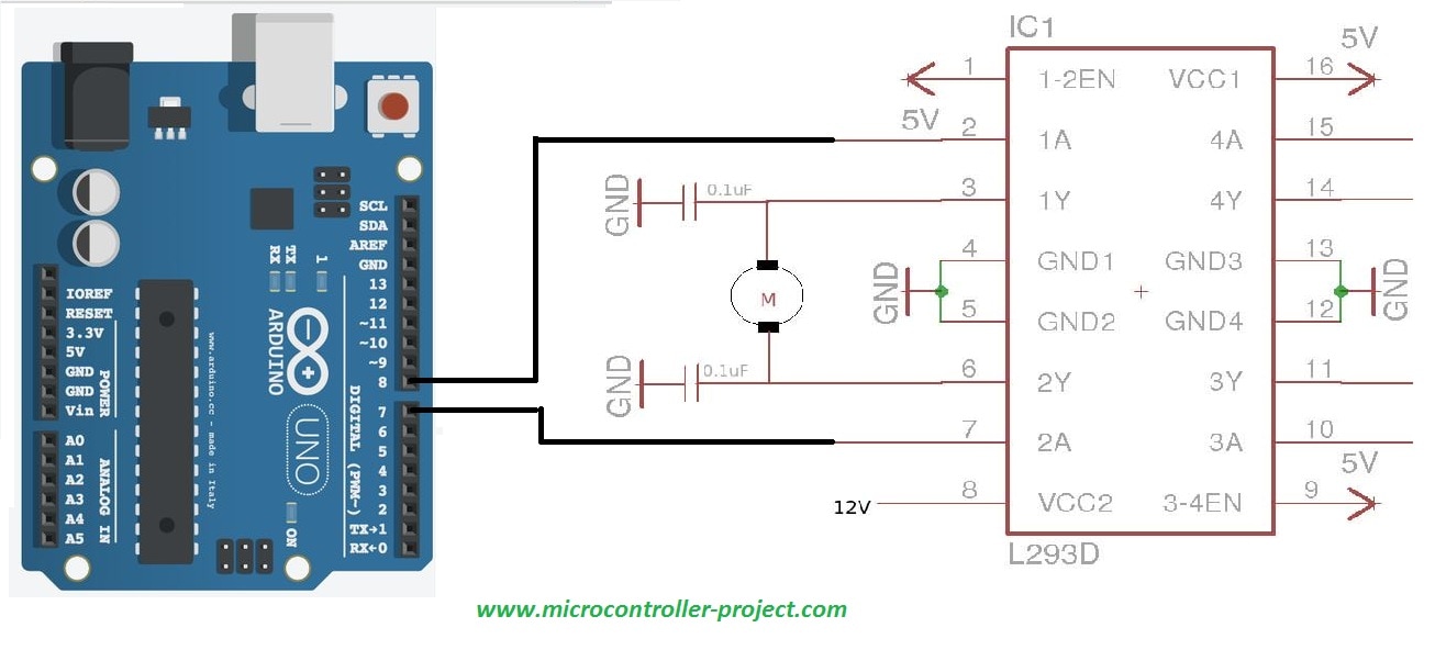

Pin 9: Enable3,4 – It is also an active high input. The supply must be connected to a source capable enough to drive the current requirement of the load. Pin 8: Vcc2 – Supply to the motors, 4.5V to 36V. Pin 7: Input 2 – Digital input to control the output 2. Motor terminals should be connected with respect to the inputs assigned. Pin 6: Output 2 – Connected to the remaining terminal of the motor 1. Pin 5: GND – Heatsink and Ground Connection. The GND connection itself used as the heat sink to disperse the heat. Pin 4: GND – Heatsink and Ground Connection. For rotating the motor in clockwise direction as well as anticlockwise direction of the input pins has to be provided signal LOW(0) and HIGH(1).Pin 3: Output 1 – Connected to one of the terminals of the motor 1 motor 1 – connected across the output 1 and 2. Let consider a Motor connected on left side output pins (pin 2,7). The motor will be rotated on the basis of the inputs provided across the input pins as LOW(0) or HIGH(1). Left input pins will regulate the rotation of motor connected across left side or motor A. There are input pins for l293d, pin 2,7 on the left as shown as on the pin diagram. Void anticlockwise() // motor rotate in backward direction Void clockwise() //motor rotate in forward direction Set the pin modes of the above IO pins to OUTPUT


Pin 16: VCC , for supply power to IC i.e 5V.Pin 15: Input B1 , when this pin is HIGH the current will flow though output 3.Pin 14: Output B1 , this pin is connected with one terminal of motor.Pin 11: Output B2 , this pin is connected with one terminal of motor.Pin 10: Input B2 , when this pin is HIGH the current will flow though output 4.Pin 9: When Enable3/Enable4 is HIGH, Right part of IC will work, i.e motor connected with pin 11 and pin 14 will rotate.Pin 8: VSS , this pin is used to give power supply to connected motors from 5V to 36V maximum depends on Motor connected.Pin 7: Input A2 , when this pin is HIGH the current will flow though output 2.Pin 6: Output A2 , this pin is connected with one terminal of motor.

Pin 3: Output A1 , this pin is connected with one terminal of motor.Pin 2: Input A1 , when this pin is HIGH the current will flow though output 1.Pin 1: When Enable1/Enable2 is HIGH, Left part of IC will work, i.e motor connected with pin 3 and pin 6 will rotate.Output Diodes for Inductive Brief Suppression (L293D).Peak Output Current 2 A Per Channel (1.2 A for L293D).Output Current 1 A Per Channel (600 mA for L293D).Wide Supply-Voltage Range: 4.5 V to 36V.Refer to the function tables below to understand unidirectional vs bidirectional motor control. L293N device can be used as a simple driver for a motor to turn on and off in one direction, and can also be used to drive a motor in both directions. The L293N device as a controller for DC motors. All inputs are TTL compatible and tolerant up to 7V. These devices are designed to drive a wide array of inductive loads such as relays, solenoids, DC and bipolar stepping motors, as well as other high-current and high-voltage loads. The L293N and L293D are quadruple high-current half-H drivers. To power the motor, we have to use an external power supply (in this project we used 9v battery), because there are hardly any motors that takes less than 500mA.
L293D MOTOR DRIVER CIRCUIT DIAGRAM WITH ARDUINO HOW TO
With this post we have have covered how to turn DC motor to the right or left and turn on and off also as per your program logic for that we have to program using Arduino IDE. You can use l298D motor driver to control small dc motors (toy motors). To achieve this, we need an integrated circuit chip (IC), called H-Bridge, we will use a L293NE for our experiment. In this tutorial, we will discuss about How to use L293 Motor Driver to control direction of motors? For this particular project we use a DC motor and try to rotate in both directions (forward and backward).


 0 kommentar(er)
